Emission Control Technology
This handbook was originally written by Gene Anguil, CEO and Founder of Anguil, as a chapter in the Odor and VOC Control Handbook by Harold J. Rafson (Editor). It has recently been updated for publication on our website to reflect vapor treatment technology advances and terminology changes.
Before reading the handbook it is important to understand that many distinctly different industries have very similar pollution control challenges as well as solutions. It is our goal at Anguil to utilize our experiences in every industry to help customers apply the proper technology on their specific application. Always feel free to contact an Anguil Representative near you to discuss your unique destruction requirements, efficiency demands and process parameters.
Chapter 8. Emission Control Technology
8.4.1 INTRODUCTION
The objective of this section is to present various VOC oxidation technologies, their strengths, weaknesses, and the elements required to determine what is the preferred technology for a given application.
Beginning in 1970, global environmental authorities started to identify various industries which had significant emissions and began establishing limits for those processes. The major industries that have employed thermal and catalytic oxidation technologies are shown in Table 8.4.1. Since the early 1990’s the baking industry, chemical process industry, pharmaceutical industry, fabric coating, rubber extrusion, electronic components, soil remediation, metal coating, wood working, formaldehyde and sterilizers have become the specific industries being targeted by the environmental authorities.
TABLE 8.4.1 MAJOR INDUSTRIAL SOURCES
Typical VOCs Emitted From Stationary Sources
| INDUSTRY | VOCS, TYPICAL SOLVENTS (S) AND OTHER OFF GASES |
| Acetate Finish Coating | Silicate Solution |
| Alcohol Synthesis | C1, C2, C3, C6 Hydrocarbons |
| Automobile Coating | Ketones, Xylene, Toluene, Phenols |
| Bakery Ovens | Ethanol |
| Can Coating | Ketones, Alcohols, Aromatic Hydrocarbons, Ethers |
| Chemical Processing | Vary Greatly |
| Coffee Roasting | Heavy Oils from coffee beans |
| Coil Coating | Phosphates, Solvesso, Cyclohexanol, Alcohols, Carbitols, Hydrocarbons |
| Electronic Components | Butyl Acetate, Xylene, MEK, Cellosolve |
| Fiberglass Coating | Teflon Emulsion, Fiberglass, Synthetics, Styrene |
| Flexographic Printing | Flexographic Ink Derivatives, Alcohols, Glycol |
| Formaldehyde | Formaldehyde, Methanol, CO |
| Lithographic Print/Paint | Butyl Cellosolve, Ciacetone Alcohol, Solvesso, Cellosolve Acetate, Xylene, MIBK |
| Metal Coating | Alcohols, Cellosolve Acetate, Phthalates, Solvesso |
| Paper Coating | High-Boiling Organics, Latexes |
| Pharmaceuticals | Isoproponol, Toluene, Hydrocarbons |
| Phthalic Anhydride Mfg. | Organic Acids |
| Resin Plant | Formaldehyde, Phenols, Phthalic Anhydride |
| Rubber Processing | Visible Smoke, Particulate |
| Soil Remediation | Benzene, Toluene, Ethylene, Xylene |
| Sterilizers | Ethylene Oxide |
| Vinyl Surgical Glove | Polyvinyl Chloride, Cioctyl Phathalate |
| Wire Enameling | Cellosolve Acetate |
Air pollution control systems for VOC abatement are typically designed around the emission constituents, concentrations, temperature and airflow volume. The volume of airflow, measured in cubic feet per minute, is designated as ACFM for Actual Cubic Feet per minute of ACFM where “S” stands for standard cubic feet per minute, at 70 degrees Fahrenheit, sea level and one atmosphere.
Single system oxidizer sizes range from 100 SCFM (160.5 Nm3/hr) up to 100,000 SCFM (160,500 Nm3/hr). Larger capacities can be achieved by putting oxidizers in series. Each industry has operations that dictate the exhaust flow that must be processed. Table 8.4.2 shows various industries and typical airflows from their operations.
TABLE 8.4.2 SAMPLE INDUSTRIAL PROCESS VOLUMES
| INDUSTRY | SCFM (Nm3/hr) |
| Soil Remediation | 100-5,000 (160.5-8,025) |
| Vent Treatment | 100-1,000 (160.5-1,605) |
| Automobile Coating | 10,000-100,000 (16,050-160,500) |
| Semiconductor | 20,000-50,000 (32,100-80,250) |
| Flexographic Printing | 5,000-50,000 (8,025-80,250) |
| Rotogravure Printing | 10,000-30,000 (16,050-48,150) |
Most oxidizers, thermal or catalytic, are pre-engineered. That is the equipment is designed in order to be competitive in the marketplace, then a series of fundamentally standard designs are tailored to the application by changing some of the parameters as dictated by the requirements. Since oxidation equipment has a burner, the designs require programmable logic controls (PLCs) to ensure safety, effective operation, and user friendly control via computer or main control panel.
Particular hydrocarbons affect human health in several ways. Some affect the respiratory system, while others are air toxins. The EPA issued new rules and regulations in 1990 regarding VOC’s and Air Toxins. Subsequent regulations have been issued which have identified that air toxins are particularly dangerous to industrial workers. One of the major air toxins is benzene, and benzene is one of the principal components of gasoline. The remediation of benzene from underground storage tanks and leaky underground petroleum bases is a significant source of air toxins. Carbon tetrachlorethylene, Hydrogen Cyanide, and Ketones are all air toxins being controlled today or being regulated, since they are carcinogenic and may create an immediate problem or delay.
8.4.2 CHARACTERIZING THE PROCESS STREAM
In determining the most appropriate technology to control a process stream, it is necessary to characterize the air stream. The first step in the characterization is to establish what organics and other contaminants need to be destroyed or controlled.
Standard forms called Application Data Sheets, are available whereby a series of questions are asked to determine which technologies can control the emissions being generated. The sizing of the equipment required is also, in part, dependent on the organic loading or concentration.
Based on removal requirements, efficiency goals and process parameters, a preferred oxidation technology can be identified. In general, low flow, low concentration streams are best handled by a catalytic recuperative oxidizer. When the concentration of the stream is between 15%-20% LEL then both a catalytic recuperative or thermal recuperative is the best technology. For process streams between 20%-25% LEL then thermal recuperative is the preferred solution.
RTO/RCO and Rotor Concentrator systems are typically higher in capital costs, but the operating cost savings on high volume, low concentration streams make these technologies attractive in this region. Subsequently the capital and operating cost of the equipment and the cost of the installation of that equipment is related to the sizing. Since oxidation equipment requires fuel and electricity, the operating costs will also depend on the hours or operation per day, per week, and per year. In addition, the costs will depend on the quantity of organics that need to be processed, in pounds per hour (lb/hr); or in parts per millions by volume (ppmv). A critical consideration is whether the organic loading is steady state or if it has peaks or spikes.
The volume of the process stream that is to be treated must be determined. Since most companies have not needed to buy pollution control equipment in the past, their approach to eliminating pollution has been the more exhaust, the better. This is particularly true in the low margin industries. The more sophisticated industries, say the chemical industry, have normally been concerned about the air exhausted from their plant and have paid attention to the exhaust volume by process control. The industries that have not paid attention to exhaust volume are not sufficiently aware that when buying pollution control equipment the cost of that equipment is going to depend on two elements:
(1) The air volume that must be processed
(2) The pounds per hour of organics that must be processed
Process flow reduction should be targeted and must be done in such a way that it will not impact upon the operation of the process or plant. The normal first response by a plant engineer is that air flow reduction cannot be done. However, subsequent investigation has resulted in that most of the time flow reduction can be done.
ORGANIC LOADING
Determining the concentration of organics is often difficult. However, in an operation where solvents or other organics are purchased, the number of pounds or tons of the organics that has been bought in the past year is known. Since this information must also be supplied to the environmental authorities. Hence, the first step that needs to be determined is done through the purchasing records. Given the tons of organics purchased in the previous years, and the number of operating hours per year, the ratio of those two numbers yields the pounds per hour, a conservative initial estimate of the average organic loading. This methodology assumes that everything that is purchased, will be emitted up the stacks.
CONTAMINANTS
It is necessary to determine if there are compounds in the exhaust stream which can be deleterious to catalyst, thereby precluding the use of this technology. As an example, when automotive catalytic mufflers and converters were introduced a number of years ago the automobile industry required the petrochemical industry to eliminate lead from gasoline since lead degraded and reduced the effectiveness of the catalyst and the destruction of the gasoline. One set of industrial compounds that can harm catalysts are halogens, a family of compounds which include chlorine, bromine, iodine, and fluorine. Bromine, while not prevalent in industry, is present in chemical plants. Freons are fluorine compounds. Silicone is another compound which is deleterious to catalyst. It is used as slip agent, or a lubricant in many industrial processes. Phosphorous, heavy metals (zinc, lead), sulfur compounds and any particulate can result in shortening the life of the catalyst. It is necessary to estimate the volume or the amount of each of those contaminants, to assess the viability of catalytic technologies for the application.
DESTRUCTION EFFICIENCY
Typically, throughout the United States 95% destruction of VOC is required, and when the more toxic Hazardous Air Pollutants (HAPs) are present then the destruction efficiency is raised to 99%. Characterization of the VOC laden stream assists in selecting the appropriate technology to achieve the required destruction rate efficiency or DRE.
MULTIPLE PROCESS LINES
If multiple process lines exist, a means to combine the airstream and to control the volume to the oxidizer must be present. For example, several process exhausts feed into the collection plenum, go through a roughing filter and are then drawn through a system fan. The pressure drop across that filter is monitored to determine when to clean the filters. The amount of flow going into the system fan is controlled by a vortex damper or alternatively, a variable frequency drive. The amount of air from multiple process lines into this plenum can vary. The pressure in the plenum is sensed by a pressure transducer and this signal is used to vary the speed of the fan VFD or position the vortex damper to control the amount of volume drawn from the plenum. Consequently, the fan will slow down or speed up until the amount of air drawn from the plenum is the same as the amount of air entering. This pressure control loop is standard on all systems that have multiple process lines. It is not required when a single process line exists, but is beneficial to minimize air volume variations drawn from the process. When a fixed speed fan is used, variation in organic loading cause differing pressure drops across the oxidizer. The differing pressure drops, result in varying flow from the process unless a pressure control loop is unitized.
8.4.3 OXIDATION TECHNOLOGIES
Oxidation, by definition, converts a hydrocarbon, in the presence of oxygen and heat, to carbon dioxide and water vapor. A general equation showing this relationship is presented in equation (1)
Cn H2m + (n + m/2) O2 → n CO2 + H2O + Heat
The particular n and m subscripts of the equation are used to define the number of carbon atoms and hydrogen atoms. The number of oxygen atoms convert to n molecules of carbon dioxide and m molecules of water vapor and heat which is given off in the exothermic reactor.
The theory of operation for thermal recuperative oxidation is called the three “Ts” of combustion:
- Time
- Turbulence
- Temperature
Time, as used in thermal oxidizers, refers to the retention time or residence which is the length of time that an organic is at the appropriate oxidation temperature. Typically, if a 95% destruction efficiency is required, a residence time of a half a second is adequate. That is, the organic if brought up to a temperature of about 1400 degrees F, and maintained at 1400 degrees F for a retention time of half a second. Both retention time and turbulence must be achieved, where turbulence is a term which implies an adequate level of mixing. If the turbulence occurs and if the 1400 degrees for a half a second is achieved, with adequate oxygen, then 95% of the organics will be destroyed. In some cases, particularly in the chemical industry, oxygen must be added to a process stream. For each organic, a specific temperature and a specific retention time is required to achieve the desired level of destruction. Table 8.4.6 illustrates these points for several organics, some being chlorinated.
There are six fundamental oxidizer technologies that achieve the oxidation of organics in alternate ways. These technologies are:
- Catalytic Recuperative
- Thermal Recuperative
- Regenerative Thermal (RTO)
- Regenerative Catalytic (RCO)
- Direct Fired Thermal and Vapor Combustors: Flare/Burner
- Ceramic Filter
Rotor Concentrators can be used in conjunction with these abatement technologies to lower volume requirements and reduce operating costs
OXIDIZER FABRICATION
Thermal oxidizers must be built to provide the residence time and temperatures to achieve the destruction of the organics. Therefore, thermal oxidizers are comparatively larger than catalytic oxidizers since their residence time is two to four times greater. Thermal oxidizers used to be manufactured with carbon steel for the outer shell and cast refractory or brick as the thermal liner. A refractory is like a cement, which is put on the inside of the rector shell to act a thermal insulation barrier. New thermal oxidizers, offered in the market place today, are designed and built using ceramic fiber insulation on the inside. This is a rather light weight material, and has a relatively long life, whereas the old refractory would tend to fail over a period of years by attrition of expansion and contraction.
RESIDENCE TIME
In the section entitled Characterizing the Process Stream, it was stated that the process air volume and the organic loading were important variables in identifying the appropriate oxidation technology. One measure of the organic loading or the organic concentration of the process stream is the “lower explosive limit”, designated as the LEL or the “lower flammable limit”, designated as the LFL. The LEL of a stream is the lowest organic concentration in a stream that would, in the presence of an ignition source, yield a combustible mixture. At this concentration, the stream is said to be at 100% LEL. As examples, if a steam has toluene or alcohol and it is at 100% LEL, this means that the concentration within that stream is explosive if a spark or ignition source is present. Characteristics of some common organics are shown in Table 8.4.5 where they are divided into five general types, Alcohols, aliphatics, aeromatics, esters, and keytones.
TABLE ORGANIC COMPOUND CHARACTERISTICS
| Gas/Vapor | Chemical Formula | LEL | Calorific Valve
(BTU/lbs) |
| (1) Alcohols | |||
| Methanol | CH3OH | 3.4 | 9,033 |
| Isopropanol | (CH3)2CHOH | 1.1 | |
| N-Butyl Alcohol | CH3(CH2)2CH2OH | 2.7 | |
| N-Propyl Alcohol | CH3CH2CH2OH | 1.2 | 12,960 |
| (2) Aliphatics | |||
| Naphtha | No chemical description | – | 16,960 |
| Methyl Cellosolve | CH3OCH2CH2OH | 1.5 | 9,274 |
| N-Hexane | CH3(CH2)4CH3 | 2.8 | 19,391 |
| N-Heptane | CH3(CH2)5CH3 | 2.4 | 19,314 |
| N-Pentane | CH3(CH2) 3CH3 | – | 19,493 |
| Dimethyl Formamide | (CH3) 2NCHO | 0.8 | |
| Cyclohexane | CH2(CH2) 2CH2 | 2.0 | 18,826 |
| (3) Aeromatics | |||
| Benzene | C6H6 | 3.2 | 17,443 |
| Toluene | C6H5CH3 | 1.7 | 17,599 |
| Tetrahydrofuran | OCH2CH2CH2CH2 | – | |
| Xylene | 17,725 | ||
| (4) Esters | |||
| Isopropyl Acetate | (CH3)2CHOOCCH3 | 12.5 | 10,960 |
| Iso Butyl Acetate | CH3COOCH2CH(CH3)2 | 6.5 | |
| Ethyl Acetate | CH3COOC2H5 | Gas | 10,235 |
| N-Butyl Acetate | CH3COOC4H9 | 3.0 | 12,460 |
| Propyl Acetate | C3H7OOCCH3 | 10.0 | 10,525 |
| (5) Keytones | |||
| Acetate | |||
| Methyl Ethyl Ketone | CH3COC2H5 | 1.0 | 13,729 |
| Methyl Butyl Ketone | CH3CO(CH2)3CH3 | 2.2 | |
| MTBK | |||
For organic benzene, it is seen that 12,000 PPM, is 100% LEL. The National Fire Protection Association (NFPA) states that equipment can operate, without LEL monitors or controls, if the LEL is less than 25% LEL. For benzene then, 25% LEL is equal to 3,000 PPM. This upper boundary becomes a dictating factor in the selection and design of the oxidation equipment. If the concentration is higher than 25% LEL, the NFPA requirements state that an LEL monitor is required. Using an LEL monitor, NFPA guidelines allow operation up to 50% LEL (a 2:1 safety factor). In summary, 100% LEL is explosive; if the stream is at 25%, a factor safety of four exists.
In addition to the explosive aspects of the LEL, another issue is the heat energy given off during oxidation. An estimate of the exotherm is that there will be a 25 degrees F rise per 1% LEL in the stream. Hence, if the process air enters the oxidizer at a given temperature, and if the stream has a concentration of 2% LEL, then a 50 degrees F rise in process stream temperature is expected after oxidation. If the process stream were running at a 10% LEL, then a 250 degrees F temperature rise would be predicted. A maximum LEL of 25%, yields a 625 degrees F temperature rise of the process stream.
The concentration that is required to yield 100% LEL varies with the characteristics of the identified organics. For example, ethanol has a 20,000 PPM by volume concentration whereas benzene has a 12,000 ppmv. Not only do different organics have different LELs but every time a pound of a different organic is oxidized, a different amount of heat will be given off. An example that demonstrates this energy release is the catalytic muffler in an automobile. When mufflers were initially installed, the high level of unburned gasoline which went through the muffler caused excessive heating and subsequently caused fires if the auto had been parked on leaves. The reason for the excessive heat was that for each pound of gasoline being oxidized 20,000 BTU’s were being released.
Chlorinated organics are hydrocarbons that have one or many chlorine atoms. Oxidation of chlorinated hydrocarbons yield CO2, water vapor and hydrogen chloride (HCl) gas. Some typical chlorinated organics are TCE and PCE. These organics have calorific values as low as 5,000 BTU/lb.
TABLE 8.4.6 TEMPERATURES AND RESIDENCE TIMES
| TEMPERATURES AND RESIDENCE TIMES | ||||
| 0.5 SEC RETENTION TIME | 1.0 SEC RETENTION TIME | |||
| 95% DE | 99% DE | 95% DE | 99% DE | |
| Toluene | 1351 | 1372 | 1317 | 1338 |
| Benzene | 1489 | 1640 | 1415 | 1640 |
| Styrene | 1445 | 1480 | 1391 | 1424 |
| PCE | 1843 | 1921 | 1726 | 1797 |
| TCE | 1592 | 1675 | 1545 | 1572 |
| PCE – Perchloroethane | ||||
| TCE – Trichloroethane | ||||
| DE – Destruction Efficiency | ||||
Toluene: 95% destruction efficiencies achieved with a half a second residence time if the temperature is 1351 degrees. At one second residence time, the temperature can be reduced slightly to 1317 degrees. To achieve 99% destruction with a half a second residence time, the operating temperature would have to be 1372 degrees F. Whereas if one second residence time existed, then 99% destruction efficiency could be achieved at 1338 degrees F. Increased temperature gives better destruction efficiency but increases operating costs. Increased retention time gives better destruction efficiency but increases capital cost. The balance between increased capital cost and lowered operating cost must be weighed.
Benzene: Benzene, which is carcinogenic, requires a higher destruction temperature than toluene. Rather than operating at 1351 degrees, operating temperatures of 1489 degrees are required at one half a second residence time.
PCE: The chlorinated organics require higher temperatures. Rather than operating at the 1400 degrees range, the oxidizer must operate around 1800 degrees , a longer residence time allows a decreased temperature to about 1700 degrees F; an increase to a 99% destruction requires an increased temperature to about 1900 degrees F.
One of the concerns that exists in thermally processing chlorinated organics is that the by-products of combustion that are formed may be more harmful than the initial product that is to be destroyed. A by-product of combustion is a compound formed, either catalytically or thermally, when most of the organic compound is converted to CO2 and H2O. For example, when 95% of Toluene is destroyed, what happens to the other 5%? Does it remain as Toluene or are new products formed? Frequently, “by products of combustion” are formed and it is not possible to predict what those by products are. They could be a mixture of the original compounds or they could be more harmful. The concern that people have in processing chlorinated organics thermally at these high temperatures is that dioxins may be generated. Dioxins are in effect much more harmful than the organic that will cause VOCs or smog in the air.
 8.4.3.1 CATALYTIC RECUPERATIVE OXIDIZER
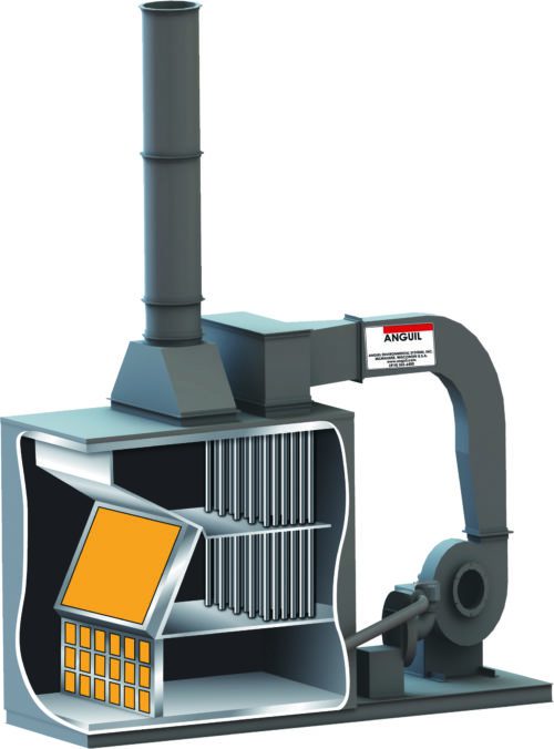
A catalytic recuperative oxidizer consists of several main elements, as shown in Figure 8.4.2, and classified as:
- System Fan
- Heat Exchanger
- Reactor
- Catalyst
- Exhaust Stack
This diagram shows a typical P & ID for such a system. The process stream is ducted to the oxidizer and enters a system fan. The system fan is driven by a motor and the process stream is forced under positive pressure through a heat exchanger. The heat exchanger shown is a cross flow heat exchanger of the shell and tube type. Plate type heat exchangers can be used in the application. Normally, the process stream enters through the tube side of the heat exchanger due to the ability of cleaning the tubes. As the air enters in and goes through the heat exchanger, it is heated and will then exit into the section called the reactor. As it comes into the reactor, the process stream will be further heated by a burner, controlled by a thermocouple measuring the temperature of the air and a temperature controller regulating the burner firing to bring the process stream up to the catalyzing temperature of 300-700 degrees F. The catalyzing temperature depends on the organic, the requirement for the destruction of the organic and the type and volume of catalyst. At the catalyzing temperature, the process stream will pass through a series of beds, having catalyst in them. As the air containing organics comes across the catalyst, the organic is converted to CO2 and water vapor and an exothermic reaction occurs. This exotherm will raise the temperature of the stream exiting the catalyst bed. Hence the catalyst outlet temperature will be higher than the temperature going into the catalyst bed. The process stream is then directed though the shell side of the heat exchanger where it preheats the incoming air and is then exhausted to the atmosphere.
CATALYST
The characteristics of oxidation catalyst are many and varied. Fundamentally, if an airstream containing organics is heated and passed across catalyst, the organics will be converted to carbon dioxide and water vapor. However, the percent conversion happens at different temperatures for different organics and for different catalysts.
Consider the compound – Toluene. To destroy 25% of the Toluene in an air stream, the chart is entered on the y axis at 25%, come over to the toluene line, and down to the Fahrenheit line, and it is seen that a temperature of about 300 degrees F is required. However, the EPA does not require 25% destruction, but 95-99% destruction. In order to destroy 95% of the Toluene, enter the graph at 95% destruction, come over to the Toluene line, down vertically and it is seen that 500-550 degree range is required in order to destroy the Toluene. Some organics require higher temperatures to be destroyed than others, catalytically. Alcohols, isopropyl alcohol and ethanol, can be destroyed relatively simply whereas the Acetates, particularly the ethyl acetates and propyl acetates, may require temperatures in the 750 degrees F range in order to achieve adequate destruction. Depending on the process stream, either a single organic may be present as found in the chemical industry, or in printing operations, a multiplicity of organics exists. Having a multiplicity of organics imposes the requirement of focusing on the ability to destroy the most difficult organic
Some organics cannot be effectively destroyed by catalyst. For example: heptane and hexane, can be destroyed at temperatures of 600-700 degrees. Whereas propane, ethane and methane require temperatures beyond a reasonable temperature range. Since methane is not a smog producing organic, a guarantee to destroy 95% of the organics means that the methane is not considered and is removed from that stream in the computation process. However, if propane is the auxiliary fuel, that is if the burners are being driven by LPG or by propane directly, it means that there will be contribution to the VOC at the end of the stack.
Catalyst samples are shown in Figure 8.4.6. Some catalyst is deposited on a ceramic substrate. These ceramics are extruded in a malleable state and then fired in ovens. The process consists of starting with a ceramic and depositing an aluminum oxide coating. The aluminum oxide makes the ceramic, which is fairly smooth, have a number of bumps. On those bumps a noble metal catalyst, such as platinum, palladium or rubidium, is deposited. The active sited, wherever the noble metal is deposited, is where the conversion will actually take place.
An alternate to the ceramic substrate is a metallic substrate. In this process, the aluminum oxide is deposited on the metallic substrate to give the wavy contour. The precious metal is then deposited onto the aluminum oxide. Both forms of catalyst are called monoliths.
An alternate form of catalyst is pellets. The pellets are available in various diameters or extruded forms. The pellets can have an aluminum oxide coating with a noble metal deposited as the catalyst. The beads are placed in a tray or bed and have a depth of anywhere from 6 to 10 inches. The larger the bead (1/4 inch versus 1/8 inch) the less the pressure drop through the catalyst bed. However, the larger the bead, the less surface area is present in the same volume which translates to less destruction efficiency. Higher pressure drop translates into higher horsepower required for the oxidation system. The noble metal monoliths have a relatively low pressure drop and are typically more expensive than the pellets for the same application.
BASE METAL CATALYST
An alternate to a noble metal catalyst is a base metal catalyst. A base metal catalyst can be deposited on a monolithic substrate or is available as a pellet. These pellets are normally extruded and hence are 100% catalyst rather than deposition on a substrate. A benefit of base metal extruded catalyst is that if any poisons are present in the process stream, a deposition of the poisons on the surface of the catalyst occurs. Depending on the type of contaminant, it can frequently be washed with water. When it is washed, abraded or atritted, the outer surface is removed and subsequently new catalyst is exposed. Hence, the catalyst can be regenerated. Noble metal catalyst can also be regenerated but the process is more expensive and often doesn’t work effectively.
A noble metal catalyst, depending on the operation, will typically last around 30,000 hours. As a rule of thumb, a single shift operation of 40 hours a week, 50 weeks a year results in a total of 2,000 hours per year. Hence, the catalyst might have a 15 year life. It may degrade, it may need some washing, it may need some other operations on it, but it should last that long. If a plant operates three shifts a week, or 6,000 hours per year, then the expected catalyst life would be about five years. From a cost factor, a typical rule of thumb, catalyst might be 10%-15% of the overall capital cost of the equipment.
For more design information visit the catalytic oxidizer page.
8.4.3.2 THERMAL RECUPERATIVE OXIDIZER
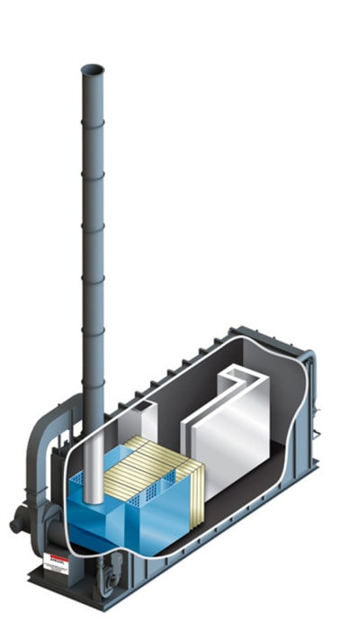 This diagram shows a forced draft thermal recuperative oxidizer, where the system fan forces the process airstream through a heat exchanger. As the process flow exits the heat exchanger the burner fires and the process stream is brought up to temperature. The reactor chamber, which is lined with a high temperature ceramic fiber, is designed for the required retention time. A shell and tube heat exchanger is normally used for thermal oxidizers because of expansion concerns. The material selection for the shell and tube heat exchanger needs to be a high grade stainless, adequate for expected steady state and peak temperatures.
The thermal oxidizer illustrated is a forced draft system, but induced draft systems also exist. The induced draft system is slightly more expensive but is recommended when particulate or organic oils are present. Particulates impact upon a forced draft fan and will have a negative effect on the system performance. If the process stream is clean a forced draft system is appropriate.
The burners employed are modulating, that is if the organic is preheated to an adequate temperature, the burners will modulate down to zero so that there is no energy required for the continued oxidation. One of the benefits of the thermal recuperative oxidizer, is that it is possible to process organics that may be a poison or be detrimental to catalyst in a catalytic oxidizer or ceramic media within an RTO. In addition, if the organic concentration is very high, for example the organic level is of the 20-25% LEL, then thermal recuperative oxidation is the appropriate technology.
The recuperative design is not recommend for large volume streams with low concentrations unless secondary heat recovery is added to capture waste heat for process heating needs. Many industries that rely heavily on thermal recuperative oxidizers will design the system with add-on heat exchangers for supplying ovens or furnaces with heat. However, without secondary heat recovery, the oxidizer is limited to 70% overall energy efficiency due to the internal metallic heat exchanger; negatively impacting energy consumption, operating costs, and greenhouse gas output.
For more information visit the thermal recuperative oxidizer page.
8.4.3.3 REGENERATIVE THERMAL OXIDIZER (RTO)
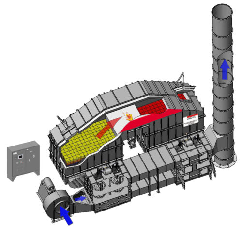 The Regenerative Thermal Oxidizer or RTO is a thermal oxidizer consisting two or more ceramic heat transfer beds, which act as heat exchangers and a Purification Chamber or Retention Chamber where the organics are oxidized and converted to CO2 and H2O vapor.
The operation of a Regenerative Thermal Oxidizer (Dual-Bed) requires the initial preheating of the ceramic heat transfer beds to a temperature of 1,300-1,500 degrees F during the start-up mode. This is accomplished by operation of fuel fired burner located in the purification chamber. To equalize the preheating of the ceramic heat transfer beds, the air is directed into and out of the ceramic heat transfer beds by operation of two (2) pneumatic diverter valves located adjacent to the ceramic heat transfer bed. During initial start-up outside air is supplied to the oxidizer through the make-up air damper tee located on the inlet side of the process air fan. A Programmable Logic Controller (PLC) monitors and controls the direction of the air flow.
After the ceramic heat transfer beds have reached operating temperature the unit is ready for the process airstream. As the process airstream enters the ceramic heat transfer beds, the heated ceramic media preheats the process airstream to its oxidation temperature. Oxidation of the airstream occurs when the auto-ignition of the hydrocarbon is reached. At this point the heat released by the oxidation of the process hydrocarbons is partially absorbed by the inlet ceramic heat transfer bed. The heated air passes through the retention chamber and the heat is absorbed by the outlet ceramic heat transfer bed. If the oxidizer is self-sustaining the net increase in temperature (inlet to outlet) is 100 degrees F.
During the normal Mode of Operation of the system the process air enters the RTO System Fan and passes through the Inlet Diverter Valve where the process air is forced into the bottom of the left ceramic heat transfer bed. As the process air rises through the ceramic heat transfer bed, the temperature of the process stream will rise. The top of the beds are controlled to a temperature of approximately 1,500 degrees F. The bottom of the beds will vary depending upon the temperature of the air that is coming in. If it is assumed that the process air is at ambient conditions or 70 degrees F, then as the air enters the bottom of the bed, the bottom of the bed will approach the inlet air temperature of 70 degrees F. The entering air is heated and the media is cooled. As the air exists the ceramic media it will approach 1,500 degrees F. The process air then enters the second bed at 1500 degrees F and now the ceramic media recovers the heat from the air, and increases in temperature. At a fixed time interval of four to five minutes, or based on thermocouple control, the diverter valves switch and the process air is directed to enter the bed on the right and exits the bed on the left. Prior to valve switching the air heated the right bed and now this bed is being cooled. The cooling starts at the bottom and continues upward because the media is hot and the energy is transferred. The process air then goes through the purification chamber and exits through the second bed.
Watch an Anguil RTO in action!
DESTRUCTION EFFICIENCY
When the valves are switched, whatever organics had not been destroyed prior to the flow being reversed are then exhausted out of the stack. In addition, the rapidity of switching or closure of the valves is critical to minimize the bypass of unoxidized organics. If the emissions vs. time were plotted, the graph would reflect a very low exhaust concentration level, say a 1 PPM, but whenever the diverter valve switches an organic pulse occurs in the exhaust stream. Since the valves shift every four minutes these pulses reduce the overall destruction efficiency of the organics. Several methods of processing the pulse exist in order to achieve higher destruction efficiencies.
OXIDIZER FABRICATION
The retention chamber and heat transfer chamber are fabricated of reinforced carbon steel exterior and ceramic fiber lining. The thickness of the ceramic fiber lining is based on the required destruction temperature of the organics and the desired outside shell temperature. The ceramic heat exchange media can be of various types including random packed or structured packing. The ceramic structured packing is a development in the industry reflecting lower pressure drops for equivalent heat transfer. A reinforced carbon steel structure is provided to support the loads of the oxidizer chambers and the structured packing support grid, and the wind and/or earthquake loads. The packing support grid is fabricated of stainless steel and is designed to support the structured packing.
DIVERTER VALVES
The oxidizer has on process air diverter valve located adjacent to the energy recovery chamber. The process air diverter valves control the process air flow into and out of the energy recovery beds. The valves can be fabricated of carbon steel or stainless steel depending on the application. The valves are operated by pneumatic actuators and controlled by a PLC to maintain optimum energy efficiency.
There are a number of different types of valves that are used. All valves must be highly reliable and have the ability to seal effectively. Many systems use heavy duty case butterfly valves, whereas newer systems utilize poppet type valves.
OXIDIZER BAKE-OUT
If organic particulates in the process exhaust builds up on the “cold” surfaces at the bottom of the oxidizer, the process must be shutdown and a volatilization of these organics or a “bake out” is required. When bake-out is activated, the flow diverter valves will stay in one position until the exhaust air temperature from the outlet bed reaches 850 degrees F. At this temperature, most organic oils will volatilize, as in a self-cleaning oven. When the first outlet bed reaches 850 degrees F, the flow diverter valves will switch and will stay in position until the outlet temperature of the second bed reaches 850 degrees F.
SUPPLEMENTAL FUEL INJECTION (SFI)
The supplemental fuel system is designed for natural gas operation, but allows the oxidizer to be operated with Natural Gas, Propane, or Butane for any condition requiring energy input to initiate or sustain operation. Supplemental fuel may be injected via the combustion burner in the Purification Chamber or by injection of natural gas properly mixed with the process stream. As the natural gas mixture rises through the ceramic media it reaches autoignition temperature and the exothermic reaction takes place, thereby providing heat to the process stream.
The benefit of natural gas injection into the process stream rather than through the burner results in utilization of 1,000 BTU/cubic feet of natural gas versus 600 BTU/cubic feet of gas, when a burner is employed.
For more information on features, benefits and components visit the regenerative thermal oxidizer page.
8.4.3.5 REGENERATIVE CATALYTIC OXIDIZER (RCO)
When catalyst is added to the media chambers of an RTO it is then referred to as an RCO. The abatement device still relies on high energy recovery to minimize auxiliary energy usage but the VOC compounds will oxidize at lower temperatures with the use of catalyst, further lowering the need for auxiliary energy. This is a great option for catalyst friendly compounds.
TABLE 8.4.8 RESIDENCE TIME (SECONDS)
| CATALYTIC VS. THERMAL
Residence Time (Seconds) 99% Destruction |
||
| Catalytic | Thermal | |
| Benzene | .18 | 1.0 |
| Carbon TET | .18 | 1.0 |
| MEK | .18 | 1.0 |
8.4.3.6 DIRECT FIRED THERMAL OXIDIZER AND VAPOR COMBUSTORS: FLARE/BURNERS
Flares are an oxidation technology that continues to be used both domestically and internationally. They are used in the petroleum, petrochemical, and other industries that require the disposal of waste gases of high concentration of both a continuous or 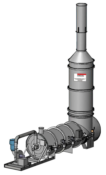 intermittent basis. As other thermal oxidation technologies, the three T’s of combustion of time, temperature and turbulence are necessary to achieve adequate emission control.
Flares ideally burn waste gas completely and without visible smoke. Two types of flares are normally employed. The first is called the open flare, whereas the second is called the enclosed flare. The major components of a flare consist of the burner, stack, water seal, controls, pilot burner and ignition system. Flares required to process variable air volumes and concentrations are equipped with automatic pilot ignition systems, temperature sensors and air and combustion controls.
Open flares have a flare tip with no restriction to flow. The flare tip being the same diameter of the stack. Open flares are effectively a burner in a tube. Combustion and mixing of air and gas take place above the flare with the flame being fully combusted outside of the stack.
Enclosed flares are composed of multiple gas burner heads placed at ground level in a stack like enclosure that is usually refractory or ceramic lined. Many flares are equipped with automatic damper controls that regulate the supply of combustion air depending on temperature which is monitored up stream of the mixing, but inside the stack. This class of flare is becoming the standard in the industry due to its ability to more effectively control emissions.
Requirements on emissions includes carbon monoxide limits and minimal residence time and temperature. Exhaust gas temperatures may vary from 1,000 to 2,000 F.
For more information visit the direct-fired thermal oxidizer or vapor combustor pages
8.4.3.7 CERAMIC FILTER
The ceramic filter collects, volatilizes and destroys particulate and condensable organics emitted from industrial process streams, such as paint spray, lost foam casting, condensable organics, tenter frames and cured rubber operations. It may be used independently as a hot or cold filter media or coupled with an oxidization module for total odor and VOC control.
The ceramic filter is designed based on exhaust airflow volume, type of contaminant and desired collection efficiency. During operation, the process stream, containing hot or cold particulate laden air, condensable organics or VOCs, is drawn into the ceramic filter. The process stream passes over a ceramic matrix selected on particle size and collection efficiency considerations.
The ceramic matrix is periodically heated by a natural gas burner, whereby any organics collected on the ceramic matrix are volatilized. Any non-organics collected on the ceramic matrix are converted to inorganic ash and retained in the unit drop out chamber. If required, the volatilized organics can then be processed through a catalyst bed. As is in the catalytic oxidizer these volatiles would be converted to CO2 and H2O.
OPERATING COST COMPARISON AND REDUCTION STRATEGIES
Since all oxidation equipment has to operate at an elevated temperature, it is necessary to know the type of auxiliary energy of fuel available. All oxidizers can operate on electric heating, natural gas or LPG, whereas the system can operate with sulfur based fuels such as number two or number six fuel oil. Electric heat is only suitable for small air flows.
Since a continuing cost of air pollution control are the operating expenses, all thermal oxidizers should have some form of heat recovery; albeit primary or secondary. Primary heat recovery refers to the heat exchange within the oxidizer itself with the use of a metal or ceramic medium. Secondary recovery is the recovery of heat exiting the oxidizer. In all systems the exiting temperatures are greater than the incoming, this temperature difference or waste heat can be recovered and utilized to satisfy other plant heating needs. The recovered heat can be used for processes such as base loading ovens or for comfort heat during the winter months.
Available heat recovery efficiencies vary depending on the type of thermal oxidation technology selected. The specific heat recovery efficiency selected for an application depends on the organic concentration. Table below shows a series of different economic analyses for a particular air stream. Click here for more information on the application of heat recovery on oxidizer systems.
TABLE OPERATING COST COMPARISONS
| Operational Costs ($/hr) | |||||
| Process Stream
10,000 SCFM (16,050 Nm3/hr) Percent LEL |
Catalytic Recuperative Oxidizer | Thermal Recuperative Oxidizer | Regenerative Catalytic Oxidizer | Regenerative Thermal Oxidizer | Rotor Concentrator with Thermal Oxidizer |
| 1% LEL | $11.00/hr | $28.37/hr | $2.50/hr | $5.65/hr | $0.30/hr |
| 10% LEL | $3.70/hr | $16.72/hr | $1.65/hr* | $1.60/hr* | N/A |
| 1. Assumes a 10,000 SCFM (16,050 Nm3/hr) process stream with an inlet temperature of 70oF. | |||||
| 2. Assumes a process mixture of 16,720 BTU/LB with a mixture LEL of 1.10%. | |||||
| 3. Assumes an electrical cost of $0.06 per KWH. | |||||
| 4. Assumes a natural gas cost of $4.50 per MMBTU. | |||||
| 5. The Catalytic Recuperative Oxidizer assumes a 65% efficient heat exchanger. | |||||
| 6. The Thermal Recuperative Oxidizer assumes a 65% efficient heat exchanger. | |||||
| 7. The Regenerative Catalytic Oxidizer assumes a 95% efficient heat exchanger. | |||||
| 8. The Regenerative Thermal Oxidizer assumes a 95% efficient heat exchanger. | |||||
| 9. The rotor concentrator wheel assumes a 6:1 concentration ratio. | |||||
| * Excess heat has been produced at this loading and a hot side heat exchanger bypass is required. | |||||
A process stream of 10,000 SCFM (16,050 Nm3/hr) with an inlet temperature of 70°F was utilized in the analyses shown here. Toluene was chosen as the contaminant in this example. Toluene has a calorific content of 16,720 BTU/LB and a LEL of 1.10% by volume. For each of the technologies, an economic analysis was performed at a toluene loading of 1% LEL and at 10% LEL. The results of this analysis are reported as operational costs in $/HR. The operational cost is the sum of the fuel usage as well as the electricity needed to run the system fans. All the technologies shown have been assumed to be running on natural gas at a cost of $4.50/MMBTU. The electricity price has been taken at $0.06/KWH.
From this table one can see the operating cost advantages of one technology over another at two loading conditions. A catalytic recuperative oxidizer, with a 65% effective heat exchanger, is more economical to operate at the 1% to 10% LEL range than a thermal recuperative oxidizer with a 65% effective heat exchanger. The thermal recuperative oxidizer will only begin to show a significant reduction in operational costs around the 15% to 25% LEL range. Both of the regenerative oxidizers utilize a 95% effective heat exchanger. These technologies are ideal for high air flow, low loading process streams. As shown, both of the regenerative oxidizers begin to show high temperature bypass at the 10% LEL loading. This means that the loading point at which the oxidizers would require zero supplemental fuel has been exceeded. Excess heat is now being produced in the oxidizer. This heat must be able to escape from the oxidizer by way of a high temperature bypass. The table also shows that the rotor concentrator wheel is another technology suited for high airflow, low loading process streams. The rotor concentrator will concentrate the process stream from anywhere between a 6:1 to a 13:1 concentration ratio. Thus, the airflow will be reduced 6 times, while the contaminant loading will be increased 6 times. The rotor concentrator technology is not suited for process streams at a 10% LEL loading.
OPERATING TEMPERATURE COMPARISONS
The oxidation temperature for catalytic or thermal oxidation is shown in Table 8.4.7.
TABLE 8.4.7 OXIDATION TEMPERATURES
| CATALYTIC VS. THERMAL
Oxidation Temperatures 99% Destruction |
||
| Catalytic | Thermal | |
| Benzene | 440 | 1460 |
| Carbon TET | 610 | 1430 |
| MEK | 600 | 1500 |
| Cyanide | 480 | 1800 |
Lower temperature, translates into lower fuel costs assuming the same heat exchanger efficiency. It takes energy to take the airstream from whatever temperature it enters, up to its operating temperature. Even though a heat exchanger will help reduce net fuel costs, the lower the operating temperature, the lower the fuel costs.
Catalytic oxidizer design uses the term Gas Hourly Space Velocity (GHSV) which relates the amount of air to be processed and the volume of catalyst required. The GHSV is the inverse of the residence time. As shown in Table 8.4.8, for Benzene destruction, the residence time in a catalytic unit, is under a quarter of a second.
Copyright 1998 by McGraw-Hill Companies, Inc. All rights reserved.